 Braceworks preferences
|
Command |
Path |
|
Braceworks Preferences |
Spotlight > Rigging |
Prior to beginning the rigging design, set the default Braceworks preferences. The settings apply to the current file.
To control automatic positioning and automatic classing options for rigging and load objects, see the Spotlight preferences: Loads and Rigging pane.
In addition to setting the preferences, specify the Braceworks units on the Structural pane of the Units dialog box. If not specified, the document units are used.
To set the Braceworks preferences:
Select the command.
The Braceworks Preferences dialog box opens.
Click the Calculation Settings tab.
Click to show/hide the parameters.Click to show/hide the parameters.
|
Parameter |
Description |
|
Safety Factors |
Sets the value of factors that are added to calculations to increase safety |
|
Preset Safety Factors |
Select a safety preset that conforms to standard safety codes; when a preset is selected, no custom modifications are permitted |
|
All Loads/Temporary Loads/ Permanent Loads |
Adds an additional multiplication factor to all loads (this factor is added to all calculations as a last calculation step), or only to loads categorized as temporarily or permanently installed |
|
Load Categories |
Adds an additional multiplication factor to the available load categories; each one can specify permanent or temporary as a sub-category for those particular load types |
|
Cable Flat-Fare |
Accounts for cable weight, without having to draw all of the cables |
|
Truss |
Adds the specified weight to all trusses (truss, straight truss, curved truss) to account for the additional weight from cables |
|
Pipe |
Adds the specified weight to all lighting pipe objects or pipe symbols to account for the additional weight from cables |
|
Calculation Settings |
|
|
Second order analysis |
Causes calculations to fail when ropes/chains receive forces they cannot support; deselect this option to ignore these failures, which allows the calculations to continue |
|
Compensate drops |
Automatically shortens drops to compensate for upper structural deflections (simulates the leveling off of lower structures) |
|
Automatic scaling |
Rescales influence lines so that they display optimally after every calculation |
|
Include references |
Allows rigging objects from referenced files to participate in calculations |
|
Maximum Allowable Deflection |
Sets the upper limit of deflection before it is considered to be “large” deflection; if this threshold is exceeded, a warning is shown. For some systems (especially very long truss lines with few supports), large deflections can occur without affecting the accuracy of the results, and this value may require adjusting. |
|
Geometry Accuracy |
Adjusts the geometric accuracy of the model; increase the value to compensate for inaccuracies, loosening the tolerance. If the value is set too high, some items will be omitted from calculations. |
Click the Results Display tab to define the classes for various Braceworks elements, to control their appearance and visibility.
Click to show/hide the parameters.Click to show/hide the parameters.
|
Parameter |
Description |
|
Influence Line Classes |
|
|
Active class |
Places influence lines in the currently active class |
|
Same class as structural element |
Places influence lines in the same class as the associated truss or other rigging object |
|
Select class |
Select a class from the list of classes present in the drawing, or create a new class |
|
Use Standard Class |
Select a class from the list of classes present in the drawing, or create a new class; the standard suggested class is selected by default |
|
Combine standard class and truss name |
Adds the name of the cross section to the selected class name |
|
Label Classes |
Select a class from the list of classes present in the drawing, or create a new class. The standard suggested label classes are selected by default. |
|
FEM object classes |
Creates additional FEM (Finite Element Model) objects and adds them to the drawing after a calculation; when deselected, no FEM objects are created. Since creating the FEM objects can take time, and they are required only in special cases, they are not created by default. Select a class from the list of classes present in the drawing, or create a new class. The standard suggested object classes are selected by default. |
|
Load classes |
To control the appearance and visibility of point loads and distributed loads, select a class from the list of classes present in the drawing, or create a new class. The standard suggested load classes are selected by default. |
|
Magnet Class |
Select a class from the list of classes present in the drawing, or create a new class. The standard suggested magnet class is selected by default. Changing this setting only affects newly placed magnets, not the magnets in existing truss symbols. |
|
Reset |
Restores the default class settings for the items in the tab |
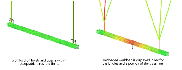
Click the Workload Display tab to specify color standards when generating a workload gradient map after calculations are complete (Braceworks required). This “heat map” applies separately to hoists/bridles and trusses, and is visible in Top/Plan as well as 3D views.
Click to show/hide the parameters.Click to show/hide the parameters.
|
Parameter |
Description |
|
Color hoists |
Select how to display the workload applied to hoists and bridles |
|
Color Hoists based on |
Absolute Workload: Creates a gradient map for hoist/bridle colors, ranging from 0 to 100% of the workload. Relative Workload: Creates a gradient map for hoist/bridle colors, from the lowest to the highest workload. Threshold: Creates a color map with defined categories to represent low, high, and overloaded hoists/bridles. |
|
Color truss results |
Select how to display the workload applied to trusses |
|
Color Truss Results based on |
Absolute Workload: Creates a gradient map for truss colors, ranging from 0 to 100% of the workload. Relative Workload: Creates a gradient map for truss colors, from the lowest to the highest workload. Threshold: Creates a color map with defined categories to represent low, high, and overloaded trusses. Influence line values: Shows the colors for the value of a selected influence line, rather than a workload. Select a force (normal or shear), torsional moment force, or bending moment force for coloring. The minimum value receives the Low workload color, and the maximum value receives the Overloaded color. |
|
Workload Threshold Assignment |
|
|
Low workload |
Click the color box to select a color to represent low workloads |
|
High workload |
Enter the threshold percentage to represent a high workload, and click the color box to select its color |
|
Overloaded |
Enter the threshold percentage to represent a workload overload, and click the color box to select its color |
